| Home › Lightning & Surges Protection › Electronic Systems Protection |
|
| |
|
|

|
|
If your supply is fused at more than 16 amps see here for suitable protectors. Application Use these protectors on low current mains power supplies to prevent transient overvoltage damage to connected equipment. Typical uses include the protection of:
Features and benefits |
|
|||||||||||||||||||||||||||||
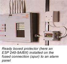
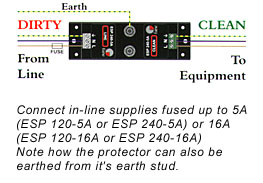
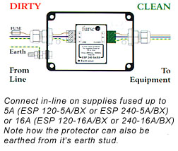
| Installation Connect in-line with the power supply usually either within the equipment panel (or for CCTV cameras, in an enclosure close by), or on the fused connection that supplies equipment. To protect equipment inside a building from transients entering on an outgoing feed (eg to CCTV cameras or to site lighting) the protector should be installed as close to where the cable leaves the building as possible. Unless ready-boxed protectors should be installed either within an existing cabinet/cubicle or in a separate enclosure. |
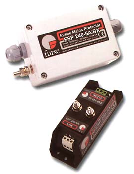
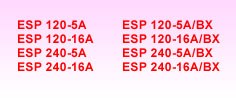
Suitable accessories If several ESP 120-5A or 16A or ESP 240-5A or 16A protectors are to be installed together, or if one is in use alongside Lightning Barriers for video or signal lines, these can be simultaneously mounted and earthed on a CMEWBX kit and housed in a suitable enclosure.
|
| Electrical specification | ||||||||||||||||||||||||||||||
|
||||||||||||||||||||||||||||||
| Transient specification | ||||||||||||||||||||||||||||||
|
| 1 The maximum transient voltage let-through the protector
throughout the test (+/-5%), phase to neutral, phase to earth and neutral
to earth. 2 Formerly IEEE 587 and ANSI C62.41. 3 Tested with 8/20µs waveshape to BS 6651:1999 Appendix C. |
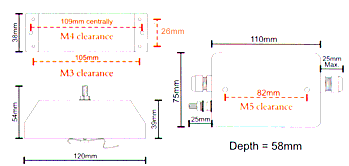
| Mechanical specification
|
|||||||||||||||||||||||||||
