| Home › Lightning & Surges Protection › Electronic Systems Protection |
|
|
|
|
|
|
|
Application Use these units to protect resistance sensitive, higher frequency or running current systems. Typical uses include the protection of:
Features and benefits
|
|
|||||||||||||||||||||||||||||||||||||||||
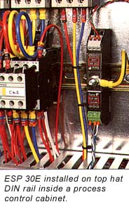
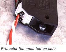
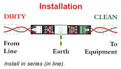
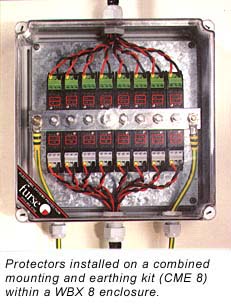
| Installation Connect in series with the data communication or signal line either near where it enters or leaves the building or close to the equipment being protected (eg within its control panel). Either way it must be very close to the systems earth star point. Install protectors either within an existing cabinet/cubicle or in a separate enclosure. If installing several protectors together these can be simultaneously mounted and earthed via a CME kit. Suitable accessories Simultaneously mount and earth up to 4 of these protectors
on a CME 4, up to 8 on a CME 8, up to 16 on a CME 16 or up to 32 on
a CME 32 - click here for details. |
|
| Electrical specification | ||||||||||||||||||||||||||||||
|
| 1 Nominal voltage (DC or AC peak) measured at <10µA
(ESP 15E, ESP 30E, ESP 50E) and <200µA (ESP 06E). 2 Maximum working voltage (DC or AC peak) measured at <5mA leakage (ESP 15E, ESP 30E, ESP 50E), <10mA (ESP 06E). |
| Transient specification | |||||||||||||||
|
| 1 The maximum transient voltage let-through the protector
throughout the test (+/-10%), line to line & line to earth. Response time
<10ns. 2 Tested with 8/20µs waveshape to ITU (formely CCITT), BS 6651:1999 Appendix C. |
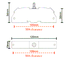
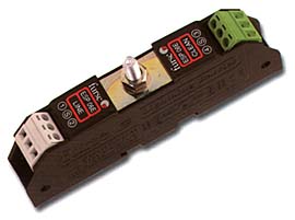
| Mechanical specification | ||||||||||||||||||||||||||||||||||||||||||
ESP E Range Brochure
|
||||||||||||||||||||||||||||||||||||||||||